


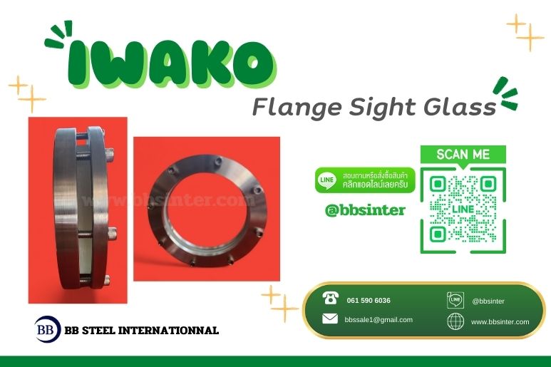
Tank Sight Glass “IWAKO”
Tank Sight Glass : A flange with a borosilicate round sight glass serves as a flanged process interface that integrates a circular borosilicate glass window so operators can visually confirm conditions inside a vessel, pipe, or equipment item without opening the system. Its engineering role is to provide a visual inspection port that remains leak-tight and pressure-capable under the specified service conditions.
This is not an instrument that produces a measured signal or value. Its function is direct observation, applied where visual confirmation is the most reliable way to answer operational questions at a specific location. In practice, it is selected to reduce uncertainty by allowing personnel to see whether the process condition at that point matches what the system is expected to be doing.
The inspection role includes verifying presence or absence of liquid, observing flow behavior near a point, confirming product appearance, checking solids behavior, and supporting cleaning verification during rinse or CIP steps. The underlying logic is straightforward: there are cases where a transmitter or switch alone cannot resolve “what is actually happening” at the location, and a properly installed sight window provides that reference without disrupting the boundary of the system.
Mechanical Configuration and Design Logic
Mechanically, the assembly combines two distinct purposes:
(1) Flanged connection (mechanical interface).
The flange provides a standardized, removable connection to a tank nozzle or piping branch. This matters operationally because installation and maintenance can be performed without cutting the line. The flange is the interface that makes the unit serviceable and replaceable in a controlled manner.
(2) Pressure-rated viewing window (process boundary).
The borosilicate glass disc acts as a transparent barrier that must withstand process pressure and temperature while maintaining clarity for observation.
A critical design point is that the flange does not hold the glass by itself. The glass must be supported by a defined seat and retained by a compression structure that distributes load uniformly. This constraint drives the configuration: the glass is not treated as a free component but as a brittle process boundary element that requires controlled support and controlled compression.
Because the sight glass disc operates as a boundary, configuration decisions revolve around how forces are introduced to the glass and how sealing is achieved. The retained disc must remain leak-tight while avoiding uneven mechanical loading conditions that would concentrate stress.
Installation Considerations
Installation is not defined by convenience; it is defined by observation value and mechanical integrity.
Placement logic.
Typical installation points are selected based on access and usefulness of the viewing location:
-
Vessel shell or head nozzles to observe mixing behavior, foam, stratification, or product condition
-
Equipment covers/housings to check internal flooding, retention, or cleanliness
-
Piping branches near critical equipment to observe entrained gas, discoloration, or solids carryover
The placement rule is simple and system-driven: install it where observation reduces operational uncertainty.
Commissioning checks that control real failure drivers.
Before putting the unit into service, a set of practical checks is required:
-
Confirm mating faces are flat and aligned to avoid mechanical strain
-
Tighten bolting in a controlled, cross-pattern sequence
-
Ensure there are no chips or scratches on the disc, especially at the edge
-
Confirm the correct gasket set is installed, noting that the glass seat gasket and the flange gasket are not necessarily the same
-
Verify the location does not invite accidental impact, and apply guarding where required
These checks exist because installation errors create the same failure mechanisms as poor design: uneven compression, strain introduced from misalignment, and surface damage that can initiate cracking.
Operating Conditions and System Compatibility
System compatibility is determined by how the assembly behaves under the operating envelope and mechanical environment defined for the service.
Why borosilicate is used in industrial service.
Borosilicate glass is selected primarily for its behavior in service:
-
Lower thermal expansion than common glass, reducing thermal stress during temperature changes
-
Better resistance to thermal shock relative to soda-lime glass, while still not being shock-proof
-
Good chemical stability in many process fluids, with compatibility needing verification for the specific chemistry
-
Stable optical clarity for inspection duties
At the same time, the glass remains brittle. Compatibility therefore is not just about surviving pressure and temperature; it is also about ensuring the system does not impose bending loads, point loads, or impact conditions that the glass cannot tolerate.
Service envelope dominates vessel suitability.
The assembly can be applied to many vessels provided the service envelope is appropriate. The limiting factors are not the vessel category itself, but:
-
Pressure/temperature excursions
-
Chemical compatibility for the specific chemistry
-
Vibration/pulsation expectations
-
Exposure to mechanical damage at the installation location
This is the correct engineering framing: a vessel may be “suitable” in concept, but the local operating and mechanical environment determines whether the sight glass remains a reliable boundary and inspection reference.
Failure Risk if Incorrectly Applied
A round sight glass disc behaves like a circular plate under differential pressure. When failures occur, they are rarely explained by “weak glass.” They are typically driven by identifiable engineering causes:
-
Non-uniform bolt preload / uneven compression induces bending stress in the glass
-
Misalignment between mating flanges/nozzle faces transfers mechanical strain into the sight glass body
-
Incorrect gasket selection leads to leakage and subsequent overtightening, increasing glass stress
-
Severe temperature transients from rapid heating/cooling cause thermal cracking
-
Surface damage such as chips, scratches, or impact initiates cracks and can lead to sudden fracture
These failure modes share a single principle: they introduce stress states or defects that the assembly is not configured to tolerate. As a result, design and installation must focus on uniform support, controlled compression, and predictable thermal behavior.
Maintenance and Inspection Considerations
Maintenance and inspection for this component are driven by the reality that the disc is a brittle boundary and the assembly relies on correct interface conditions.
The practical inspection logic is captured by commissioning and in-service checks that focus on:
-
Alignment of mating faces, since misalignment drives strain into the assembly
-
Condition of the glass disc, specifically the presence of chips or scratches, with particular attention to the edge
-
Confirmation of the correct gasket set, since gasket mismatch or unsuitable selection can start a leak-tightness problem chain that ends in overtightening and increased glass stress
-
Environmental exposure to impact, since mechanical damage risk at the installation location directly affects reliability
Because the assembly is a flanged, removable interface, the system can be serviced without cutting the line. That only remains true in practice when bolt tightening and gasket management are controlled, rather than improvised.
Engineering Decision Criteria
Engineering selection and evaluation should be anchored to specifying the minimum data that prevents misapplication and field rework.
A) Define the flanged interface.
-
Standard (e.g., ASME/ANSI, DIN, JIS)
-
Size (DN/NPS)
-
Pressure rating (PN/Class)
-
Facing type (RF/FF/RTJ)
These characteristics determine nozzle interchangeability and sealing behavior.
B) Define the operating envelope.
-
Normal operating pressure and maximum credible pressure (including surges/upsets)
-
Normal operating temperature and maximum/minimum temperature
-
Temperature cycling profile (start-up/shutdown, washdown, CIP transitions)
C) Define process fluid exposure.
-
Fluid identity and concentration for compatibility verification
-
Presence of solids/abrasives/crystals because these elevate erosion and optical degradation risk
D) Define glass requirements.
-
Borosilicate confirmation, disc diameter, thickness
-
Edge condition/finish requirements because edge defects are high-risk
-
Clarity expectations for the inspection duty
E) Define gasket requirements.
-
Gasket material for the glass seat and for the flange joint
-
Compatibility with process chemistry and temperature
F) Define mechanical environment constraints.
-
Vibration/pulsation expectation
-
Impact exposure risk and need for protection/guarding
A practical boundary condition closes the decision loop: if a supplier cannot confirm the assembly’s pressure/temperature capability for the stated conditions, there is no design basis—only a guess. The engineering decision is then incomplete, regardless of procurement progress.
Upgrade your tank inspection reliability with Tank Sight Glass “IWAKO.”
Engineered for stable pressure containment and clear process visibility, it provides dependable performance where visual confirmation matters most.
Contact our technical team today to request a quotation or submit your operating conditions. We will verify flange specification, pressure rating, temperature range, and gasket compatibility to ensure the correct configuration for your system.
Secure the right Tank Sight Glass “IWAKO” for your application—built for industrial performance, specified with engineering precision.
BB STEEL INTERNATIONNAL
Tel. 061 590 6036
Line ID : @bbsinter
E mail : bbssale1@gmail.com
FACEBOOK บีบี สตีล อินเตอร์เนชั่นแนล
Author Profile

Latest entries
 level gaugeสิงหาคม 24, 2026Industrial Welding Pad Level Gauge Supplier “IWAKO”
 level gaugeสิงหาคม 21, 2026Water Liquid Level Gauge Cock Stainless Steel “IWAKO”
 strainer filterสิงหาคม 17, 2026Automatic water filter used for water treatment
 strainer filterสิงหาคม 17, 2026Automatic self-cleaning filters IWAKO ระบบบำบัดน้ำเสียและน้ำบริสุทธิ์ที่โรงงานไว้วางใจ
